Design Guidelines for Precision Die-Cut Adhesive Parts
A die-cut part is only as producible as its drawing. Most tooling problems, part defects and cost overruns we see come from five predictable design choices. These guidelines are based on what our rotary and flat-bed dies actually cut in production, not textbook theory.
1. Minimum web and bridge width
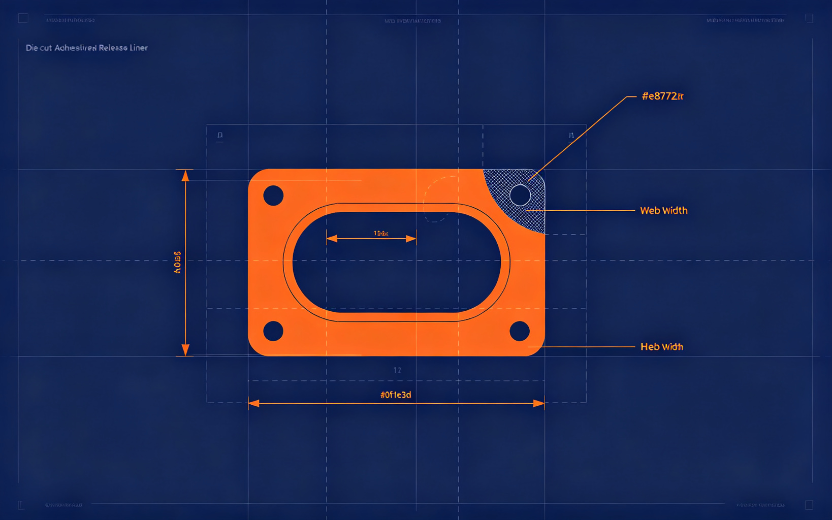
Never design a web narrower than the material thickness (for film) or 1.5× the material thickness (for foam or rubber). A 0.1 mm PET web in a 1 mm foam part will tear on the matrix and force a re-tooling. When the part pattern has many holes, call out a minimum web on the drawing — it saves a design review cycle.
2. Inside corner radius
A razor knife cannot cut a true sharp inside corner without a radius. Specify an inside radius of at least 0.3 mm; on thick foams (≥1 mm), use 0.5 mm or larger. Sharp internal corners fracture the die steel and produce ragged edges. If a sharp corner is functionally required, plan a secondary post-punch step rather than expecting the die to do it.
3. Hole and cut-out size
The smallest reliably punched hole in film is roughly 1.5× the material thickness; in foam, 2× thickness. A 0.5 mm hole in a 1 mm foam pad will not hold tolerance and may bridge. Design holes larger than this, or switch to a rotary or laser process for micro-features.
4. Tolerance callout
Do not put ±0.05 mm on every dimension. That tolerance is achievable on flat-bed or laser cutting but not on high-speed rotary — and it doubles tooling cost. Put tight tolerances only on the critical mounting holes and assembly interfaces; leave general dimensions at ±0.15 mm (film) or ±10% thickness (foam).
5. Release liner and orientation
Specify which side faces up on the liner, the liner colour, and whether kiss-cut matrix needs grid lines for automated pickup. Missing these notes is the most common cause of a first article that does not match assembly expectations.
Send us your drawing before tooling. Our DFM team reviews it free and flags every dimension that will cost you money or delay the sample.
Request a free DFM review of your drawing →
6. Die cutting vs Form-In-Place (FIP): which gasket route fits your volume?
FIP (Form-In-Place) gaskets are dispensed as liquid silicone or urethane directly onto the housing by a robot, then cured in place. Die-cut gaskets are converted from finished foam, rubber or adhesive sheet stock in our workshop. FIP suits large sealing beads, complex 3D paths and low part-count tooling; die cutting wins on precision, thin sections, repeatability across many identical parts and unit economics at volume. For most EMI gaskets, foam seals and adhesive parts, die cutting is the lower-cost, faster-to-market route — and it lets us ship finished parts on liner, ready for assembly.
Still deciding? Send us your drawing — we will quote both a die-cut and an FIP-compatible design so you can compare cost and lead time.