Your Trusted Partner in Precision Die Cutting Manufacturing
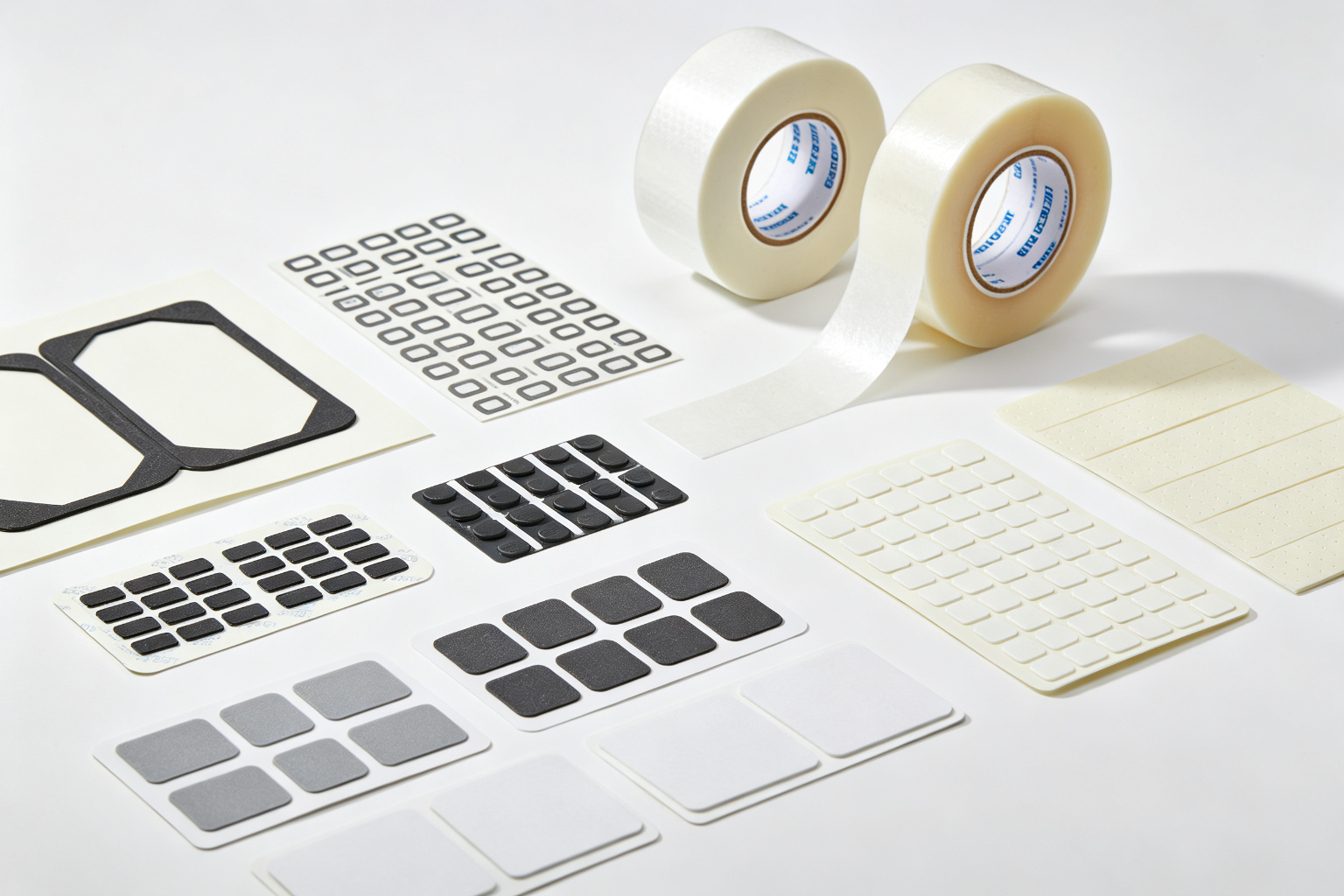
Founded in 2015, Shenzhen Fangying Technology Co., Ltd. is a professional precision die-cutting and adhesive material manufacturer. We specialize in precision die-cutting of double-sided tapes, VHB tapes, foam tapes, thermal conductive silicone pads, insulating sheets, custom gaskets, protective films, OCA optical adhesives, thermal management materials, copper/aluminum foils, and EMI shielding materials. Our die-cut components serve a wide range of industries including plastics, hardware, mobile phones, automotive, computers, flexible printed circuits (FPC), and industrial control.
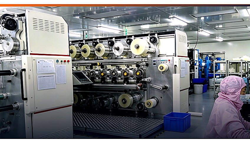
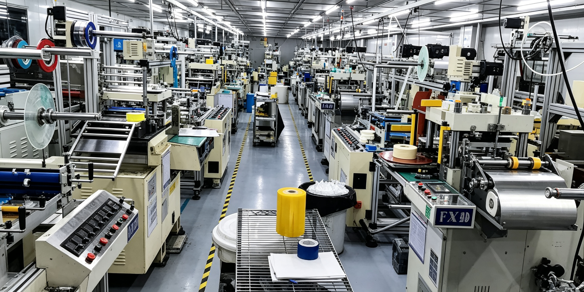
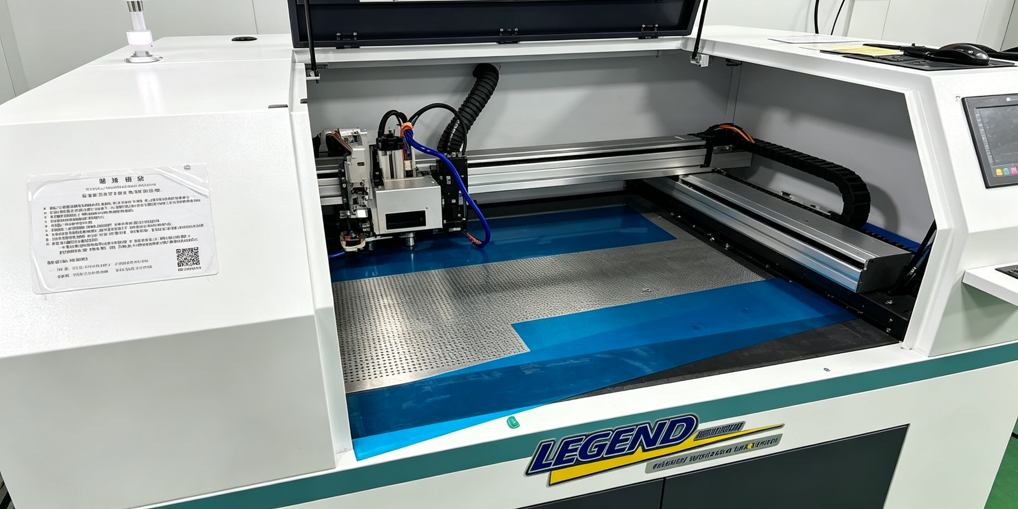
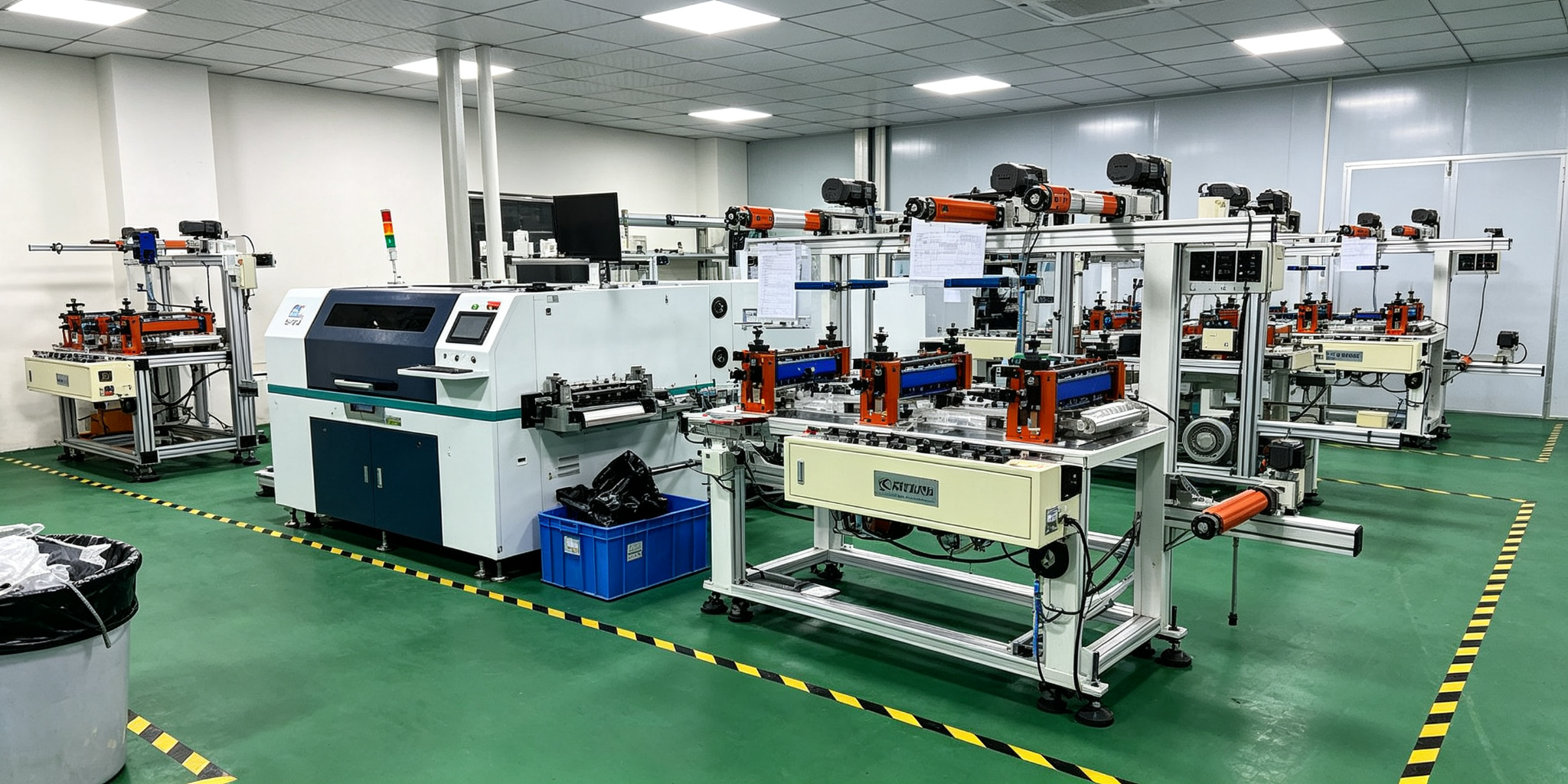
The company is equipped with industry-leading automated die-cutting production equipment, including rotary die-cutting machines, flat-bed die-cutting machines, and laser cutting machines. We deliver proven and practical die-cut design solutions to meet your specific bonding and assembly requirements.
Teamwork, Innovation, and Excellence! Guided by our core values of "customer focus, quality first, and continuous improvement", we are committed to delivering high-quality products and services to our customers.
Custom Solutions
Tailored die-cut designs for your specific application needs
Fast Delivery
7-15 day lead time with rapid prototyping services
Quality Assured
ISO certified with 100% full inspection before shipment
Expert Team
30+ technicians with 6+ years of industry experience
Our Products
Comprehensive Die-Cut Adhesive Solutions
We manufacture precision die-cut products using premium materials from leading brands including 3M and TESA, serving consumer electronics, automotive, medical and industrial markets worldwide.
01
Conductive Fabric & EMI Gaskets
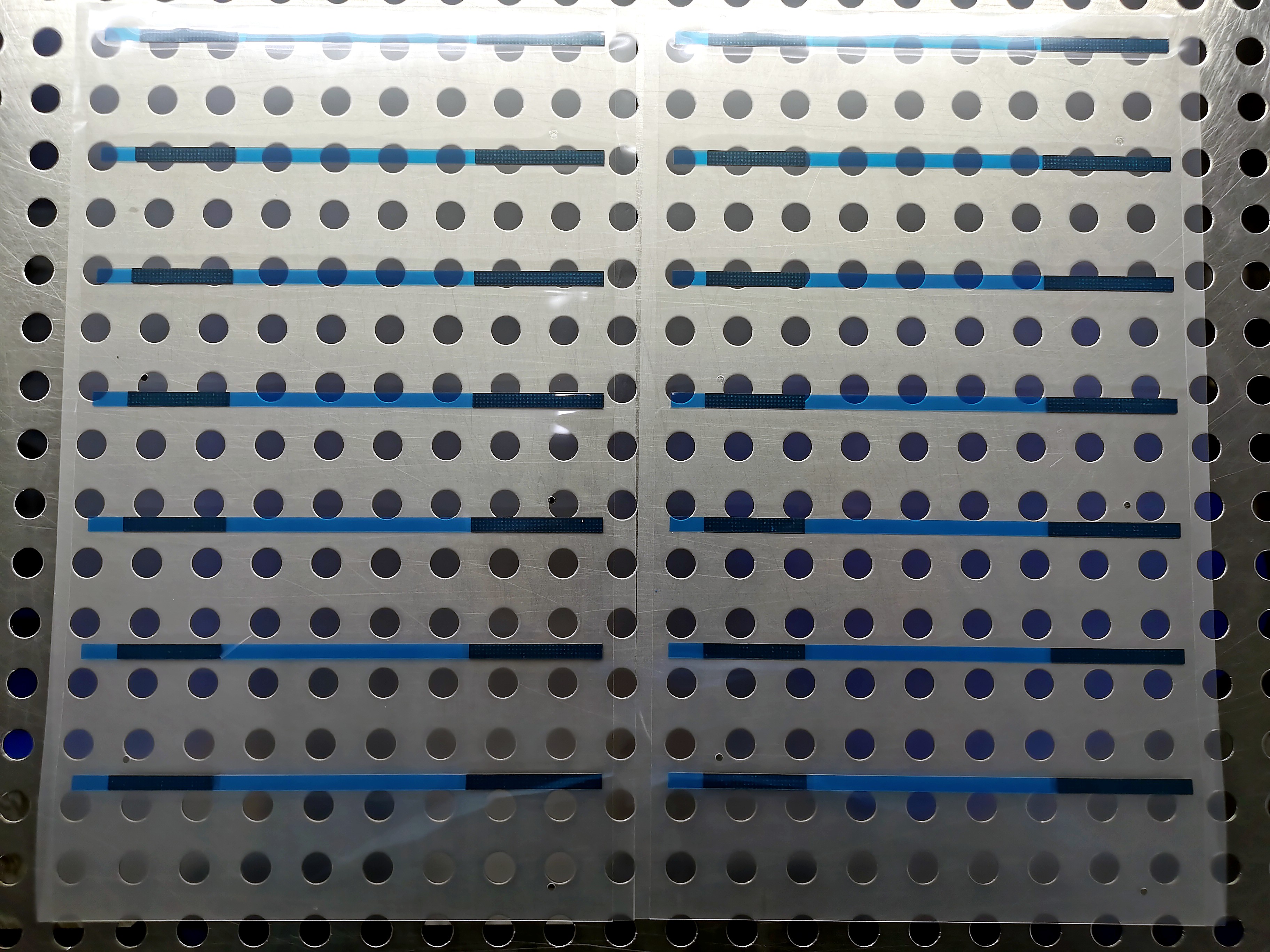
Copper/nickel/silver-plated polyester fabric delivers flexible, low-resistance EMI shielding (60–90 dB). Conductive adhesive films use silver/copper/nickel-filled acrylic on PET, fabric, or foam carriers — available in isotropic (3-axis) or anisotropic (Z-axis) construction for both bonding and electrical continuity. Engineered for consumer electronics, displays, and automotive applications: EMI gaskets, grounding pads, FPC bonding, and component retention. Precision die-cut to your drawings, with configurable adhesive and non-adhesive zones for high-volume automated assembly.
60–90 dB ShieldingIsotropic / Z-AxisEMI Gaskets
02
VHB Acrylic Foam Tape
High-strength bonding solutions for automotive and home appliance industries. Closed-cell acrylic foam with excellent temperature resistance and water resistance.
3M 49203M 49303M 4951
03
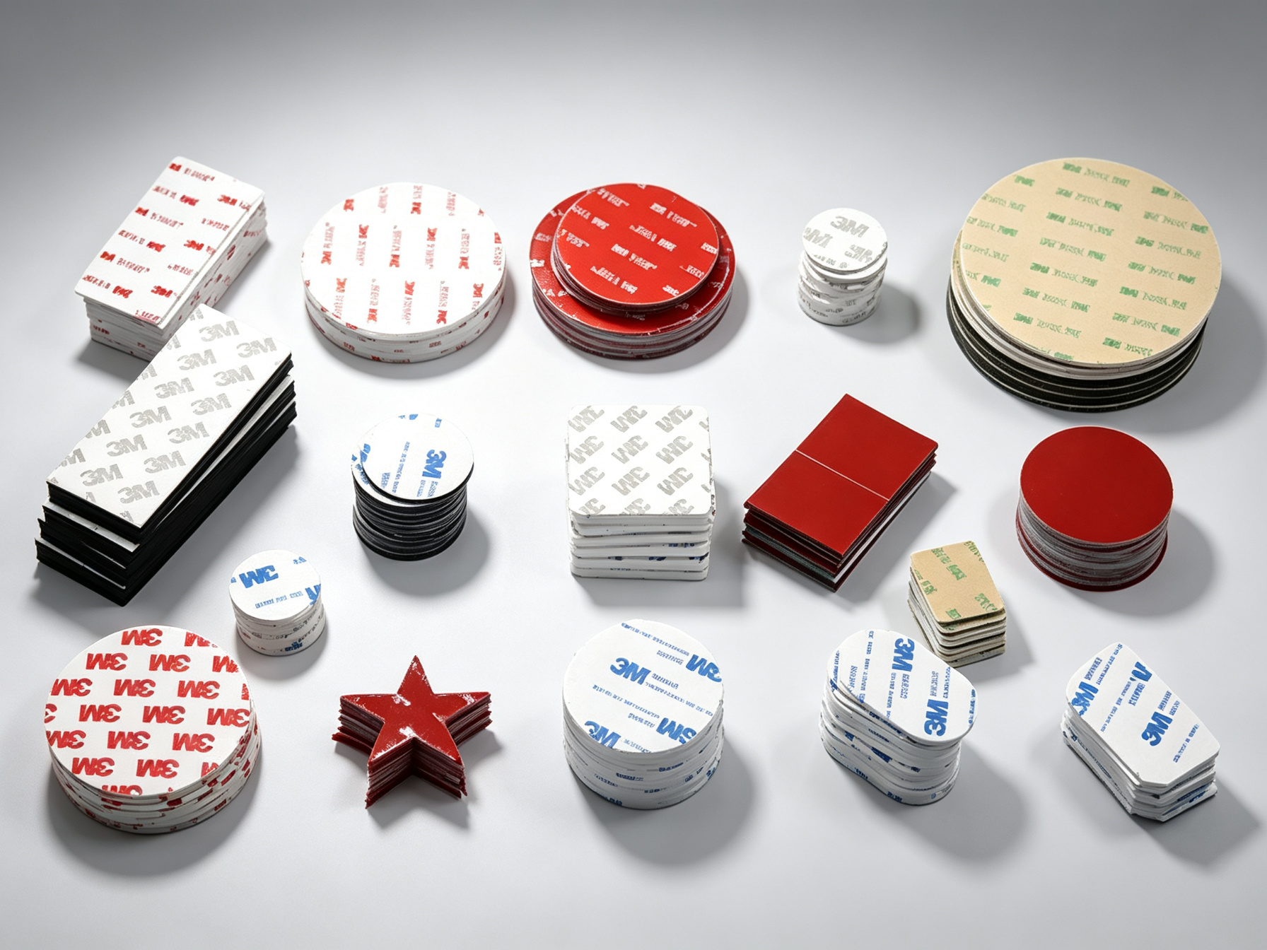
3M Series Custom Die-Cuts
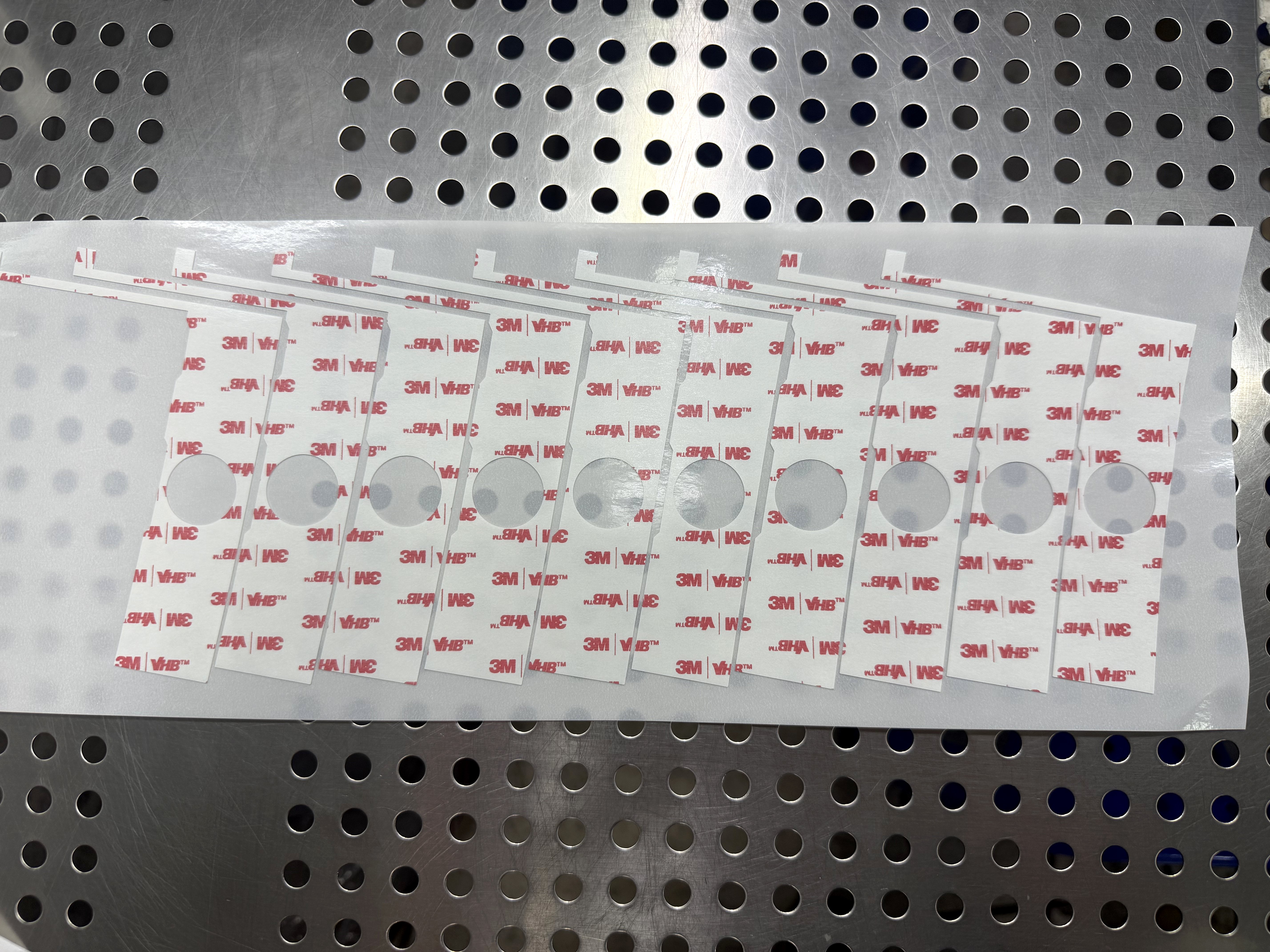
High bonding strength, shock absorption, temperature and aging resistance, water and moisture resistant. Can be die-cut to any shape and size, replacing screws and rivets to simplify assembly. Ideal for electronic component mounting, nameplate bonding, automotive parts, home hardware, and plastic/metal part bonding.
Using 3M MaterialsCustom ShapesHigh Bonding
04
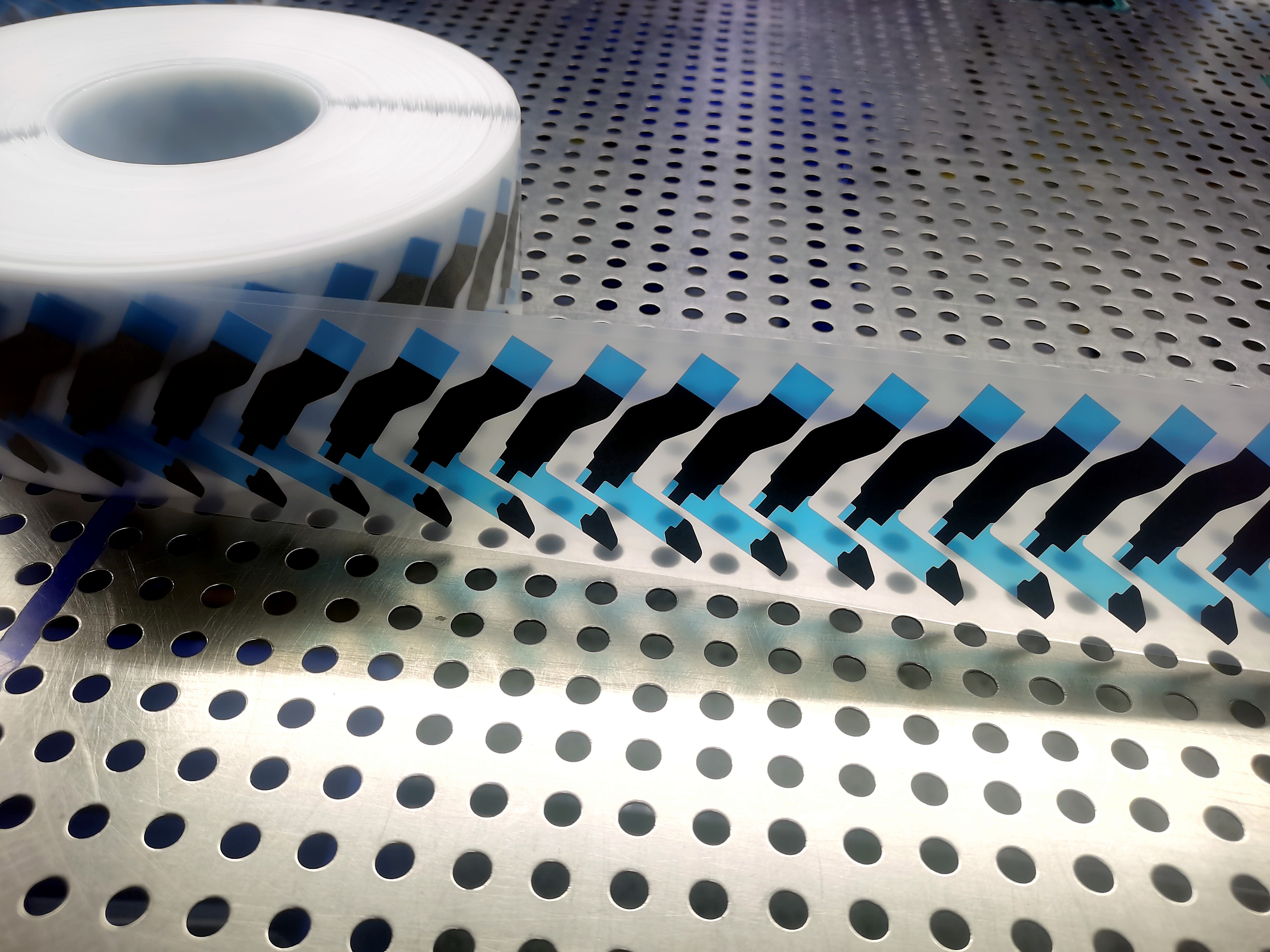
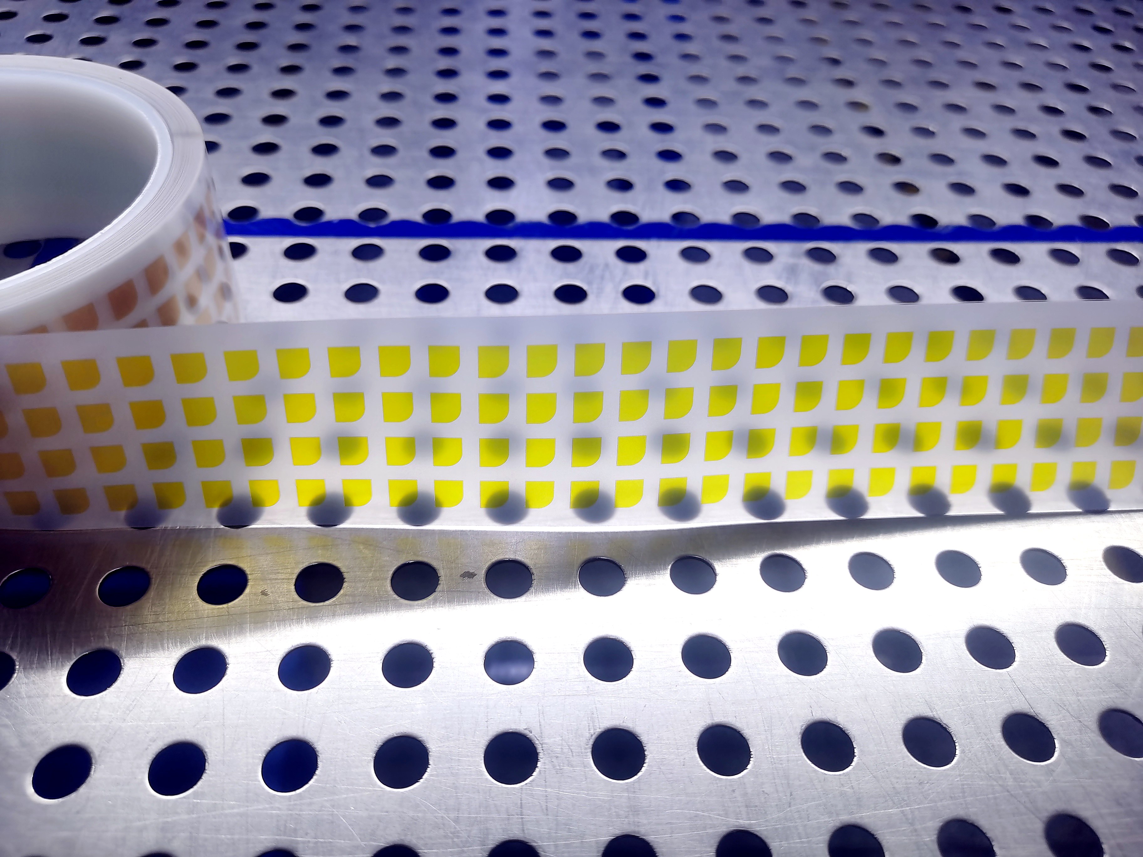
Roll-Fed Tape for Automated Assembly
Roll-form double-sided tape (also called jumbo-roll or roll-stock double-coated tape) is a pressure-sensitive adhesive tape supplied in continuous roll format. It is coated with adhesive on both sides and backed by a release liner (paper or film) on one face. Unlike precut sheets or individual die-cut pieces, its primary advantage is that it is designed for automated, high-volume production. The entire process—unwinding → lamination → die-cutting → liner rewinding—runs continuously in a single pass with minimal manual handling. It is widely used across the electronics, automotive, and home appliance industries for large-scale bonding and tape-backing operations.
Roll-FedPick-and-PlaceHigh-Speed
05
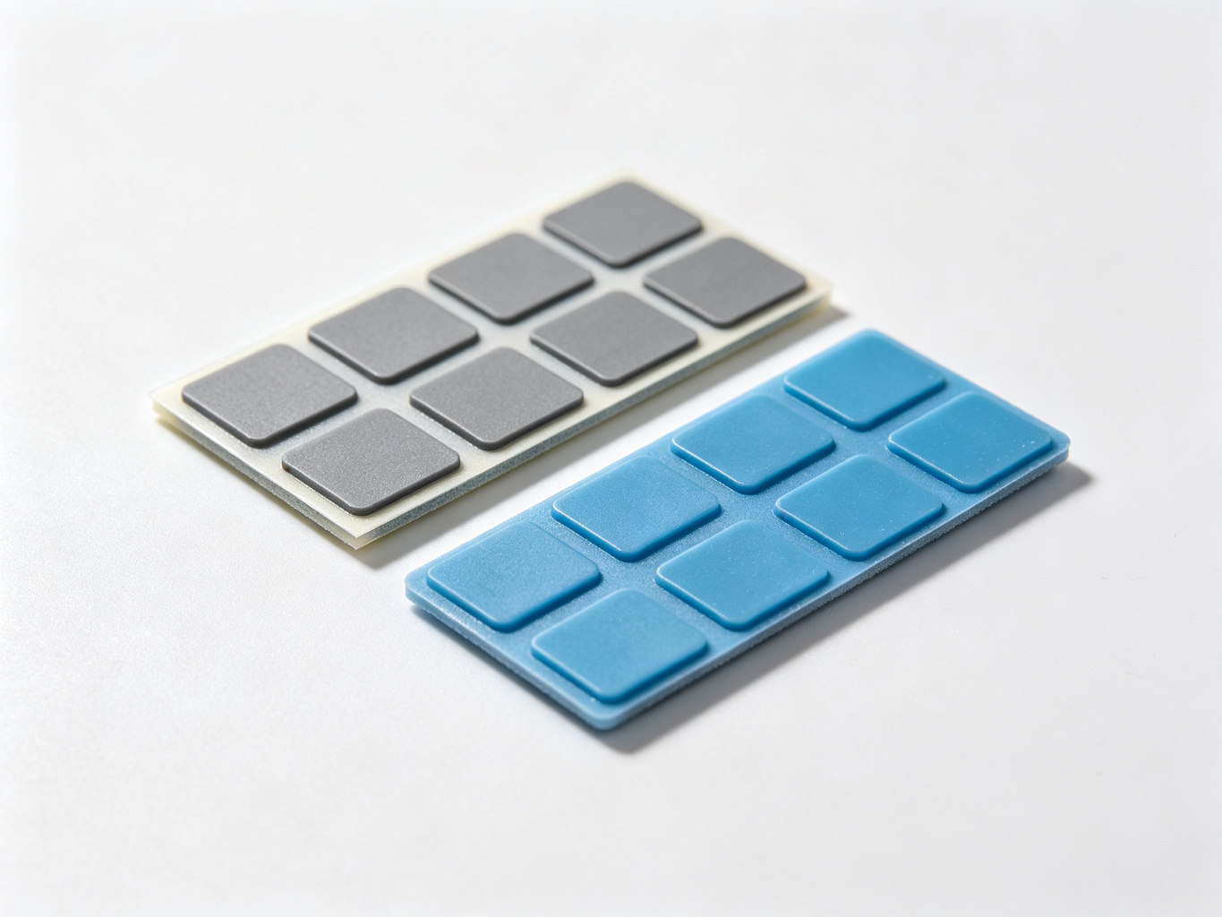
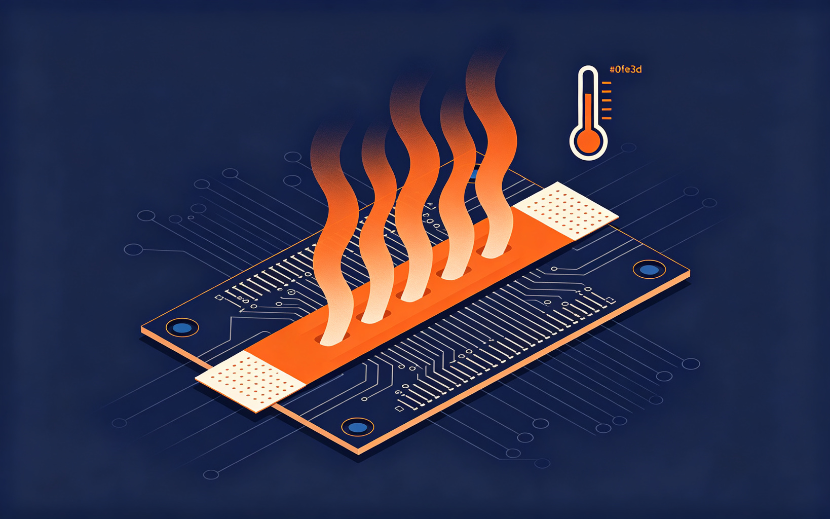
Thermal Conductive Materials
Thermal double-sided tapes and silicone thermal pads die-cut to specification. High thermal conductivity, low thermal resistance, and high compressibility. Flame retardant and insulating, effectively fills assembly gaps. Essential for CPU, GPU, power supplies, battery modules, LEDs, and renewable energy electronics.
Thermal PadsHigh ConductivityCustom Sizes
06
Polyimide (PI) High-Temperature Tape
A polyimide-film-based insulating tape with a high-temperature silicone PSA. Standard thicknesses are 25 μm and 50 μm; rated −269°C to +260°C continuous, Class H, UL94 V-0, residue-free after soldering. Used for PCB gold-finger masking, SMT reflow/wave-solder protection, lithium-battery insulation, motor/transformer winding, and aerospace harnesses. Pick 25 μm for fine-pitch work, 50 μm for general insulation.
25μm / 50μmUL94 V-0SMT / PCB
07
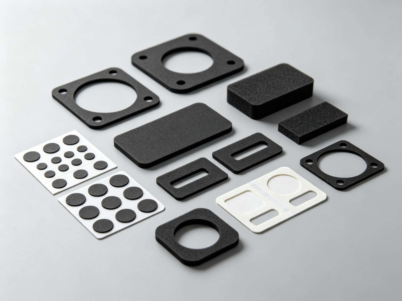
Custom Die-Cut Foam Gaskets
We specialize in custom die-cut foam gaskets in PU, PORON® (Rogers), and EVA. The foam is laminated with pressure-sensitive adhesive (PSA) on one or both sides, then precision die-cut to your drawings. Widely used for dust sealing, EMI shielding, and shock absorption in consumer electronics, wearables, and automotive electronics.
PORON® / PU / EVADust & EMI SealShock Absorption
08
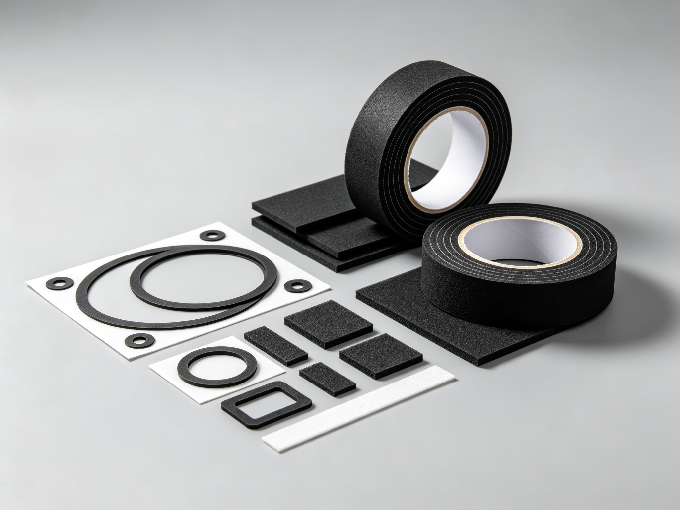
PE Foam Double-Sided Tape
A sealing and cushioning tape built on a closed-cell polyethylene (PE) foam backing, coated on both sides with acrylic pressure-sensitive adhesive (PSA). Standard thickness: 0.15–3.0 mm. The closed-cell structure delivers IPX7 waterproofing (IPX8 for cross-linked grades). The foam compresses 20–40% to fill gaps and absorb shock, and is easily die-cut into custom gaskets and shapes. Widely used for display and battery sealing in consumer electronics, interior bonding in automotive, panel mounting in appliances, and sealing in window/door and solar PV assemblies.
IPX7 / IPX80.15–3.0 mmDie-Cut Gaskets
09
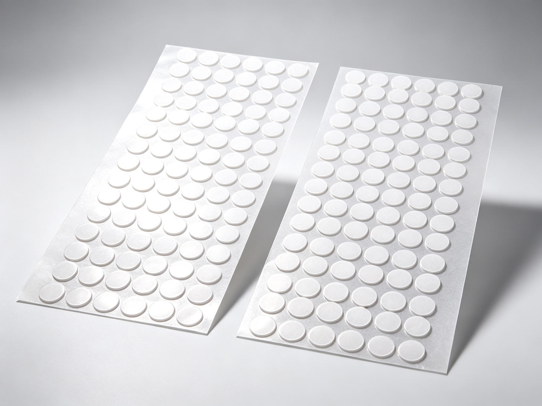
Removable Traceless Adhesive Pads
Removable and residue-free adhesive pads. Waterproof and high load-bearing capacity. Can be die-cut to various shapes and sizes without damaging walls. Ideal for traceless hooks, shelves, and small household item bonding. Suitable for smooth surfaces such as tiles and glass.
RemovableTracelessWaterproof
Production Equipment
Advanced Manufacturing Capabilities
Equipped with industry-leading automated production machinery to ensure precision, efficiency, and consistent quality for every order.
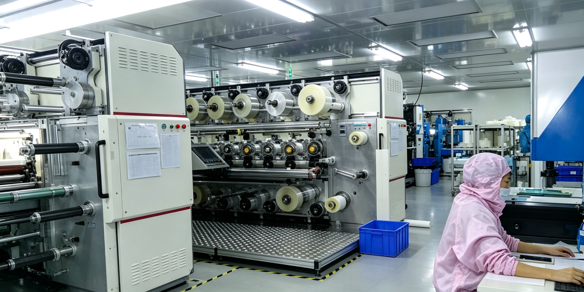
16-Station Rotary Die Cutting Lines
2 Production Lines
Multi-station rotary die cutting production lines for complex multi-process products. Enables simultaneous lamination and die-cutting of roll materials, significantly improving production efficiency for high-volume orders.
Flat-Bed Die Cutting Lines
11 Lines | 28 Machines | 39 Laminators
Combination flat-bed die cutting lines with synchronized lamination for both roll and sheet materials. Configured to meet various production line bonding requirements across different product types and materials.
High-Precision Laser Cutting Systems
4 Laser Machine Sets
Advanced laser cutting for dense multi-hole adhesive parts and harder materials. Supports rapid small-batch production and fast prototyping with exceptional precision and consistent quality.
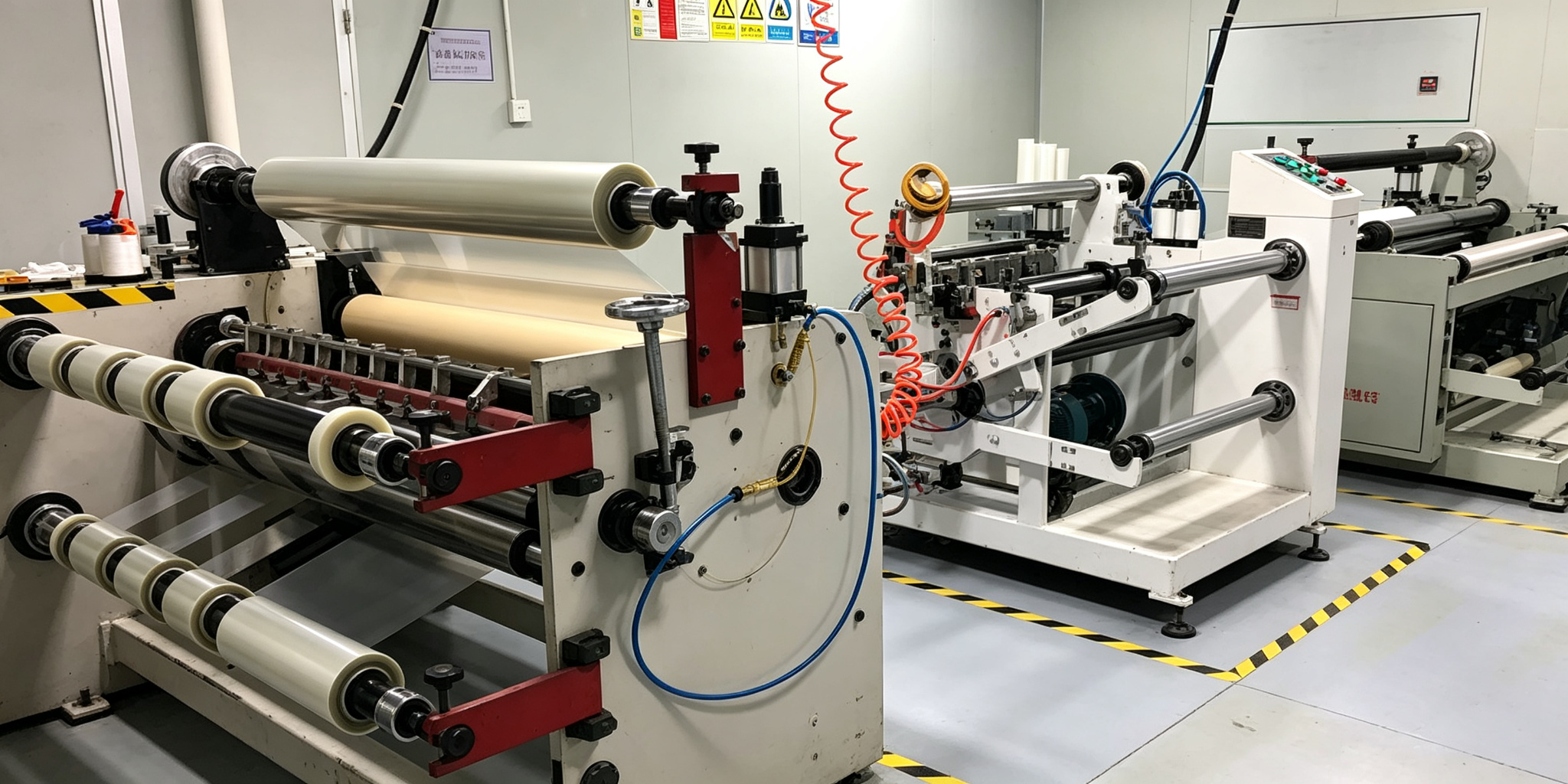
Slitting & Cutting Equipment
1.3m Wide Slitter | Auto Cutter
1.3m wide slitting machine for protective films, release films, and foam materials. Fully automatic cutting table for double-sided tapes, conductive fabrics, and high-temperature adhesives with precision width control.
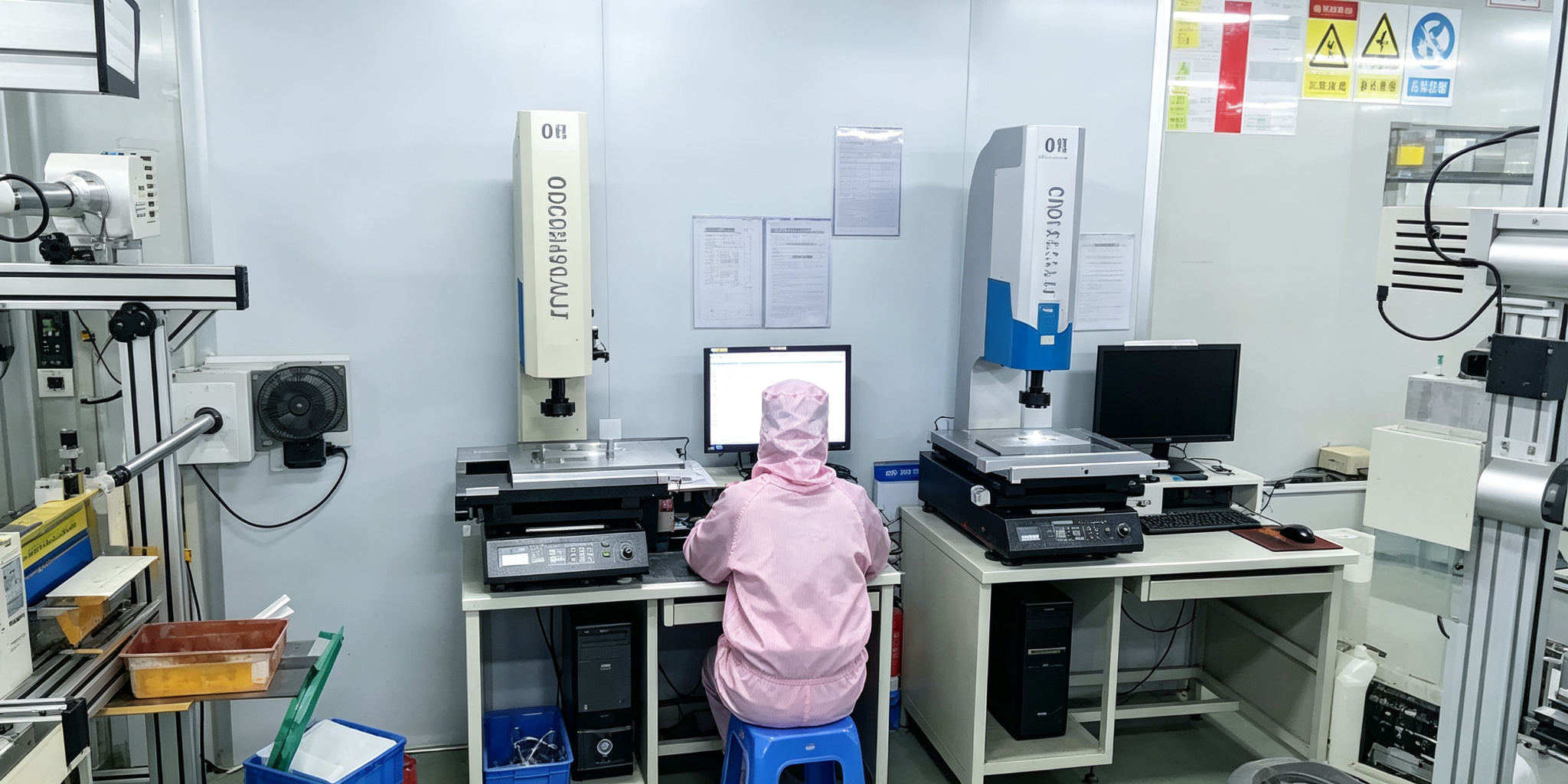
Quality Testing Instruments
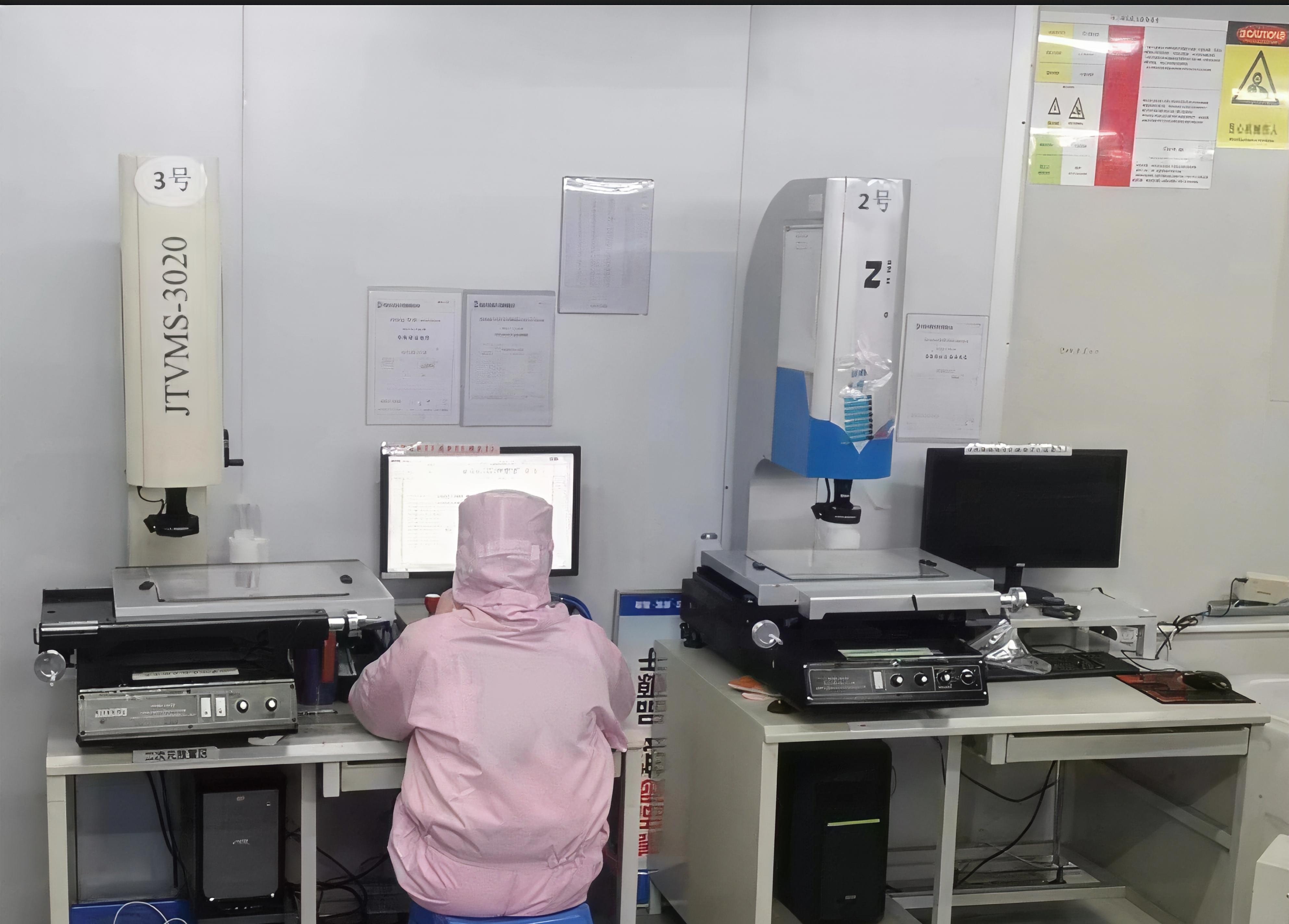
2D Measuring | Tensile Tester | Climate Chamber
Comprehensive quality control equipment including 2D coordinate measuring instruments for dimensional inspection, tensile testers for adhesive peel strength testing, and constant temperature/humidity chambers for environmental simulation testing.
Engineering & Design Capability
Senior Engineering Team
Experienced engineering design team delivering proven and practical die-cut product design solutions. We work closely with customers to optimize product geometry, material selection, and manufacturing processes for cost-effective production.
Precision Manufacturing at Scale
With our advanced equipment configuration and experienced team, we maintain high production capacity across various product types. Our 30+ skilled technicians each bring 6+ years of machine operation experience, ensuring consistent quality and on-time delivery.
Quality & Certifications
Committed to Excellence in Every Product
Quality is the foundation of our business. We maintain a comprehensive quality management system with dedicated quality personnel at every stage — from incoming material inspection to in-process monitoring and final outgoing inspection. Every product we ship undergoes 100% full inspection to ensure it meets your specifications.
ISO 9001:2015Quality Management System
ISO 14001:2015Environmental Management System
REACH-SVHC CompliantEU Chemical Substance Regulation
SGS RoHS CompliantRestricted Substances Tested
Why Choose Us
The Fangying Advantage
We combine advanced equipment, experienced personnel, and rigorous quality control to deliver exceptional value to our global customers.
Design Expertise
Senior engineering team delivers proven, practical die-cut design solutions tailored to your specific bonding and assembly requirements.
Quality Control
Dedicated quality personnel at every stage with professional testing equipment. 100% full inspection on all outgoing products.
Fast Delivery
Efficient order review and streamlined production planning. 7-15 day standard lead time with rapid prototyping for new projects.
Skilled Workforce
30+ experienced machine operators with at least 6 years of industry experience, supported by a rigorous assessment and training system.
How It Works
From Drawing to Delivery in 5 Steps
A transparent, low-risk path from your first inquiry to mass production — with free samples and first-article inspection before any order.
1
Inquiry
Send drawings, samples or specs. Quote within 24 hours, in English.
2
Free Samples
Prototypes in 3–7 days. NDA available on request for your designs.
3
First Article
Dimensional & material verification with inspection report before ramp-up.
4
Mass Production
7–15 day lead time, 100% full inspection on every batch.
5
Global Shipping
DHL, FedEx or sea freight. RoHS & REACH docs included with shipment.
FAQ
What Buyers Ask Us
The questions purchasing teams from North America and Europe ask most before placing a trial order.
What is your MOQ (minimum order quantity)?
There is no rigid MOQ. We accept trial orders as small as 500–1,000 pieces for most die-cut parts to let you validate quality and fit before commitment. MOQ drops significantly at mass-production volumes; send us your annual estimate for tiered pricing.
Can I get free samples before committing to a bulk order?
Yes. Standard stock material samples are free; custom die-cut prototypes typically take 3–7 days. You only cover international courier cost, which is deductible from your first production order.
Do you support EU compliance — RoHS, REACH, and material declarations?
All materials we process are SGS-tested RoHS compliant and REACH-SVHC compliant. We provide material declarations (SDS), COA and first-article inspection reports with every shipment. If your product requires additional certifications (UL, IATF 16949, ISO 13485), tell us at inquiry stage and we will confirm material compatibility.
How do you protect my drawings and intellectual property?
We sign your NDA before any engineering discussion and have a long-established confidentiality workflow. Drawings are restricted to your dedicated project team, tooling is labeled with your part number, and nothing developed for you is reused for other customers. We take customer privacy very seriously — all of your business materials, drawings, specifications and data are kept strictly confidential, and will never be disclosed to any third party without your written permission.
What is your typical lead time and how do you handle quality issues?
Prototype 3–7 days, standard production 7–15 days. Every order is 100% inspected before dispatch. If any incoming lot does not match your approved sample, we cover replacement freight and rework — our quality guarantee is stated on every quotation.
Blog
Technical Insights & Buying Guides
Practical engineering and sourcing advice on die-cut adhesives, gaskets, thermal materials and international compliance — written for engineers and purchasing teams.
Material Selection
Acrylic vs Silicone Adhesive Tapes: How to Choose for Your Die-Cut Project
Temperature range, chemical resistance, release liner options and bonding surfaces — the practical trade-offs between acrylic and silicone systems.
6 min read·Material Selection
Material Selection
Which Foam Material Is Best for Shock Absorption & Sealing?
PU, PE, EPDM, silicone and PORON compared by compression set, temperature range and water sealing performance.
7 min read·Material Selection
Material Selection
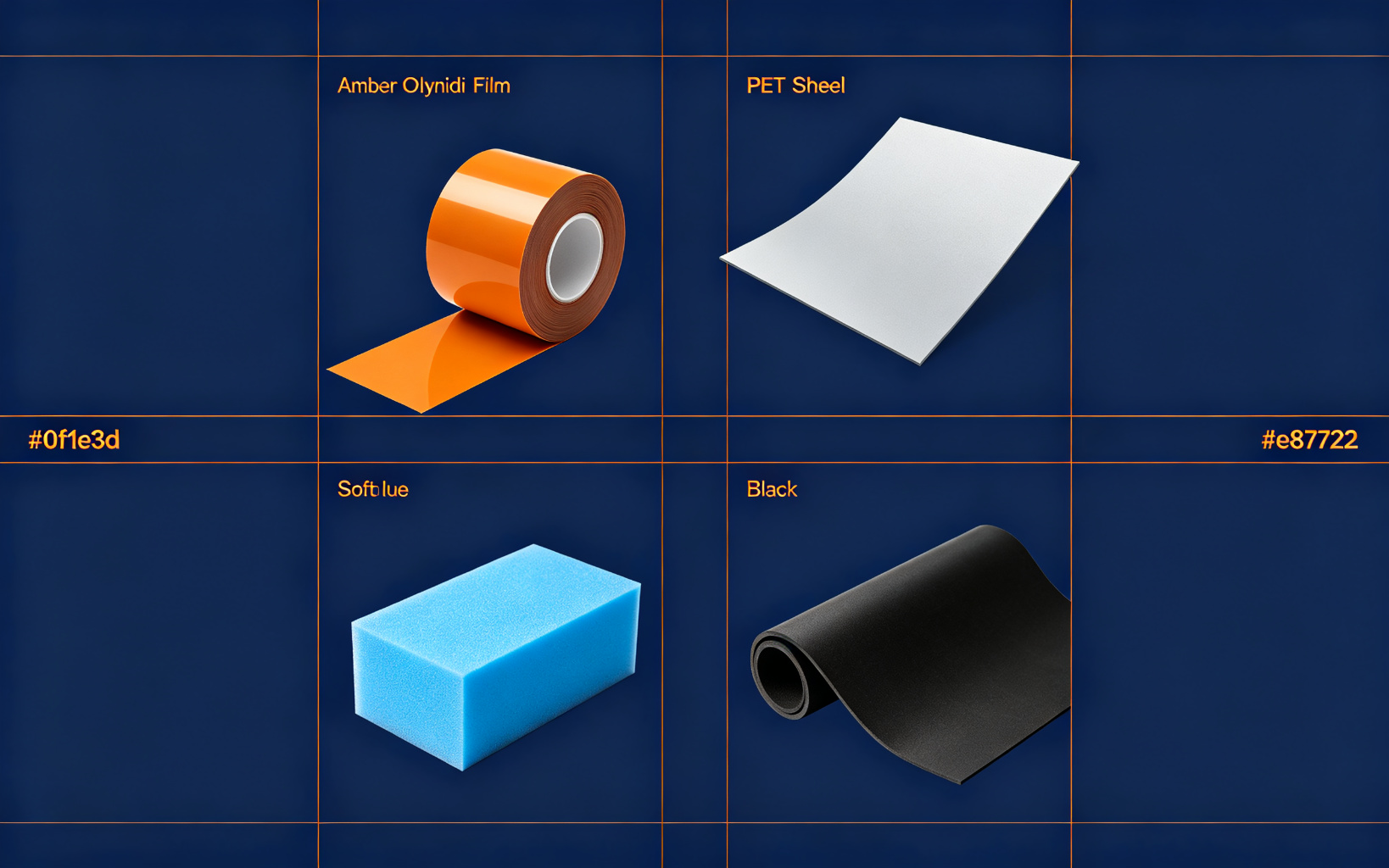
PET, PI, Foam, Rubber: Common Substrates for Precision Die Cutting
When to use polyester film, polyimide, foam or rubber — thickness, temperature and insulation properties at a glance.
5 min read·Material Selection
Material Selection
How to Select Double-Sided Tape for High-Temperature Applications
From reflow soldering to under-hood use — continuous vs peak temperature, carrier choice and failure modes to avoid.
6 min read·Material Selection
Design & Engineering
Design Guidelines for Precision Die-Cut Adhesive Parts
Wall thickness, corner radius, feature size and clearance — the design rules that keep your parts producible and cost-effective.
8 min read·DFM Guide
Design & Engineering
Tolerance Standards for Custom Die Cutting
What accuracy rotary, flatbed and laser cutting can realistically hold — and how to specify tolerances on your drawing.
6 min read·DFM Guide
Design & Engineering
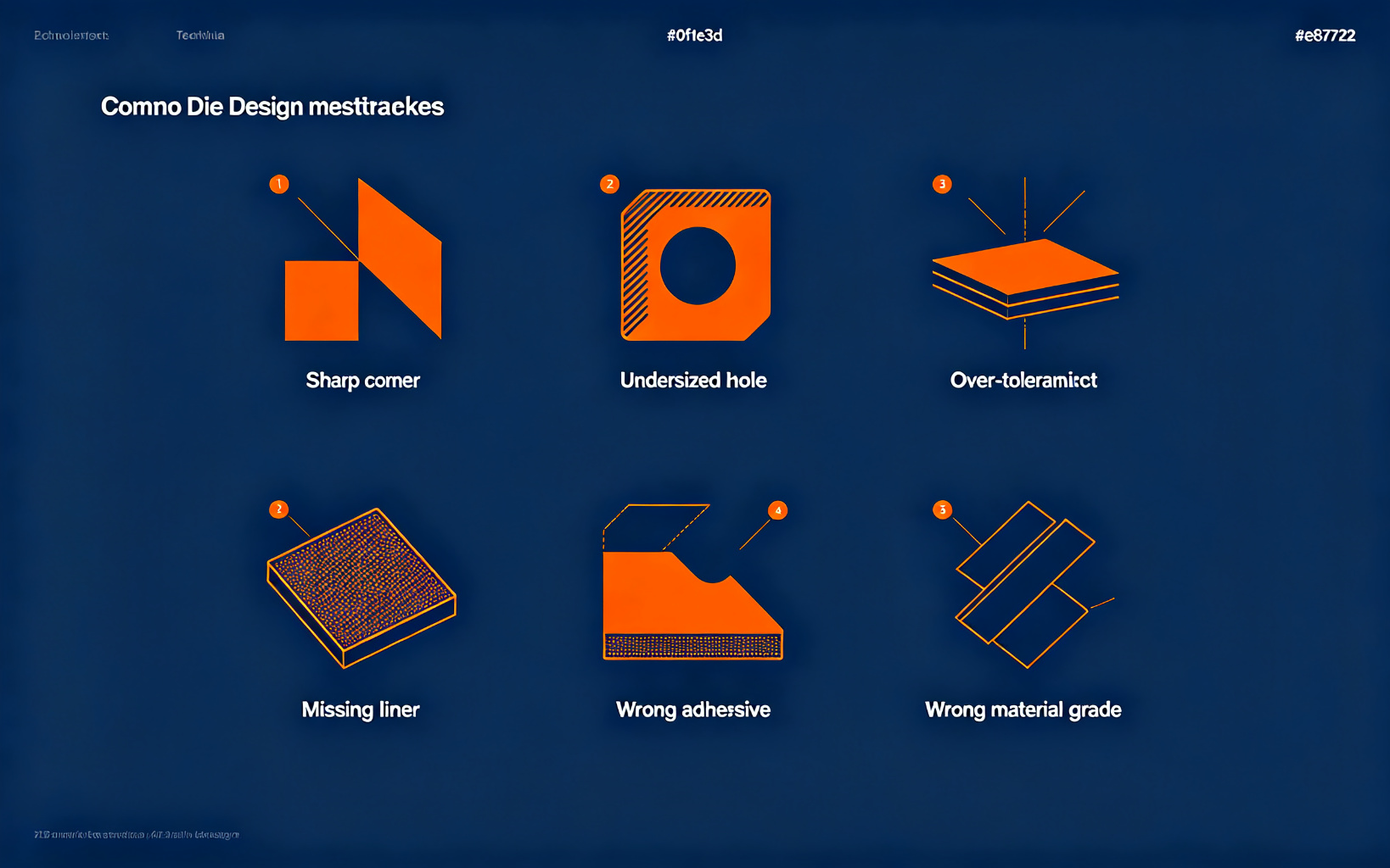
Common Die-Cutting Design Mistakes & How to Avoid Them
Too-narrow webs, wrong corner radii, missing release liner notes — the design errors that drive up cost and delay samples.
7 min read·DFM Guide
Design & Engineering
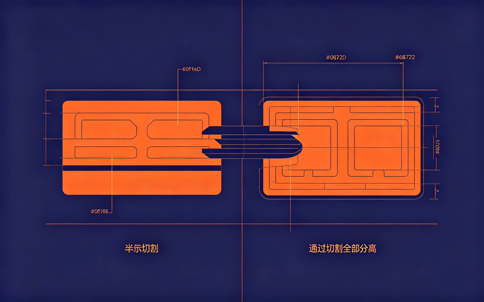
Kiss Cutting vs Through Cutting: When to Use Each Process
Die on the liner vs die through the part — automation, assembly and material selection decide which process wins.
5 min read·Process Guide
Get a Free Quote & Free Samples in 24 Hours
Send your drawing or a sample — our engineers reply within one business day, in English.
Ready to find the perfect die-cut adhesive solution for your application? Contact us today for a free consultation and custom quote. Our engineering team is ready to help you select the right materials and optimize your design.
Monday - Saturday: 9:00 AM - 6:00 PM (GMT+8) We typically reply within 24 hours. WhatsApp and email are monitored for urgent inquiries outside office hours.
Chat on WhatsApp
Open WhatsApp on your phone, tap Settings → QR Code, and scan to start chatting with our sales team.
We value your privacy. We and our partners use cookies and similar technologies to store and/or access information on your device, for site functionality, analytics, and marketing. You may accept all, reject non-essential cookies, or customize your choices. You can change your settings at any time via the "Cookie Settings" link in the footer. See our Cookie Policy and Privacy Policy.
Cookie Preferences
Choose which categories of cookies you allow. Strictly necessary cookies are required for this site to function and cannot be switched off.
Strictly Necessary
Required for core site functions such as remembering your consent choice and security. Always active.
Analytics
Helps us understand how visitors use the site (e.g. page visits, bounce rate) via first-party and third-party analytics. Not loaded until you consent.
Marketing
Used to measure the performance of advertising campaigns and enable retargeting on other platforms. Not loaded until you consent.
Shenzhen Fangying Technology Co., Ltd. ("Fangying", "we", "us") respects your privacy and is committed to protecting your personal data. This policy explains what we collect, why, and the rights you have under the EU General Data Protection Regulation (GDPR) and the California Consumer Privacy Act / California Privacy Rights Act (CCPA/CPRA).
1. Data controller
The controller responsible for your personal data is:
Inquiry data you provide: your name, company, email address, phone number, product category of interest, and the project details or drawings you submit.
Technical data: IP address, browser type, and — only with your consent — analytics events such as pages visited.
We do not knowingly collect special categories of personal data.
3. Why we use it (purposes & legal basis)
Respond to your inquiry and prepare a quote / sample — necessary for taking steps at your request before a contract.
Communicate about your project and order — necessary for contract performance.
Email marketing, only if you opt in — based on your consent; you can unsubscribe at any time.
Website analytics and improvement — based on your consent; off by default.
Legal and compliance — to meet tax, customs and contractual obligations.
4. Who we share it with
We do not sell or rent your personal data. We share data only with trusted processors who help us run this business: our website hosting provider (Vercel, Inc., USA), our form-submission service (Formspree, Inc., USA, which delivers inquiry emails to our inbox), and freight forwarders (when you place an order). These parties may only process data on our documented instructions.
5. International transfers
Your data is processed in China and may be accessed by our service providers outside the EEA/UK/USA. Where required, transfers to countries without an adequacy decision are covered by appropriate safeguards, including EU Standard Contractual Clauses. You may request a copy by contacting us.
6. How long we keep it
Inquiry and order records are retained for up to 3 years after our last interaction (or longer where tax/customs law requires). Marketing contacts are kept until you unsubscribe. Analytics data is aggregated and deleted or anonymized within 26 months.
7. Your rights
If you are in the EEA, UK, or Switzerland (GDPR): you have the right to access, rectify, erase, restrict, and port your personal data, to object to or withdraw consent at any time, and to lodge a complaint with your local data protection authority (for example, the Autoriteit Persoonsgegevens in the Netherlands, the ICO in the UK, or the CNIL in France).
If you are a California resident (CCPA/CPRA): you have the right to know what personal information we collect, to request deletion, to correct inaccurate data, and to opt out of the "sale" or "sharing" of your information for advertising. We do not sell or share personal information as those terms are defined under the CCPA/CPRA, and we do not offer financial incentives tied to personal data. To exercise any right, email sales@fawin.cn. We will respond within 45 days.
8. Children
This site is for business customers; we do not knowingly collect data from anyone under 16.
9. Changes
We may update this policy; the "last updated" date above reflects the latest version.
This site uses cookies and similar browser storage under the EU ePrivacy Directive and GDPR. Strictly necessary storage is always active; analytics and marketing storage loads only after you give consent via our cookie banner.
What we use
Strictly necessary: remembers your cookie-consent choice (stored locally in your browser) so the banner does not reappear; enables core layout and security. Cannot be switched off.
Analytics (opt-in): page-view and interaction measurement, used only after consent. Currently no analytics script is loaded until you choose "Accept All" or enable Analytics.
Marketing (opt-in): conversion tracking and retargeting pixels. Not loaded without your explicit consent.
Managing your choices
Click "Cookie Settings" in the footer at any time to change or withdraw consent. You can also clear stored site data in your browser settings. Withdrawing consent does not affect the lawfulness of processing that happened before withdrawal.
Content on this site is for general information about Shenzhen Fangying Technology Co., Ltd. and our products. You may view it for business purposes and may not republish, scrape, or use it for resale without our written permission.
2. Inquiries & quotations
Submitting the inquiry form is a request for a quote, not a binding order. Quotations, prices, lead times and specifications are confirmed in writing before production. We sign an NDA before reviewing your proprietary drawings.
3. Intellectual property
All drawings, designs, tooling and materials you provide remain your property. Product images, text and branding on this site are owned by Fangying.
4. Liability
While we keep technical information accurate, specifications can change and images are illustrative. To the extent permitted by law, we are not liable for decisions made solely on website content; formal acceptance criteria are agreed on each purchase order.
5. Governing framework
These terms and any resulting commercial contract are governed by the laws applicable to the agreed jurisdiction in the purchase order. For disputes we first seek good-faith resolution. Privacy matters are handled under our Privacy Policy.
Acrylic vs Silicone Adhesive Tapes: How to Choose for Your Die-Cut Project
6 min read · Updated September 2026
For engineers specifying a die-cut bonding component, the choice between acrylic and silicone adhesive is rarely decided by peel strength alone. The two chemistries behave very differently on low-surface-energy plastics, under thermal cycling, and when the bonded assembly has to survive decades in the field. This guide compares them across the parameters that actually drive field failure.
1. Surface energy: the first filter
Acrylic adhesives bond best to surfaces above ~38 dynes/cm — treated metals, glass, ABS, PC and PET. On HDPE, PP, powder-coated or silicone-rubber surfaces, standard acrylic will delaminate regardless of how high the initial peel number looks on the datasheet. Silicone adhesive tolerates low-energy surfaces down to ~28 dynes/cm and is the default choice for bonding silicone keypads, rubber gaskets or fluoropolymer films.
2. Temperature range
Acrylic foam tapes (VHB family): continuous use typically −40 °C to +150 °C; peak exposure up to +200 °C for short cycles. Suitable for most electronics and appliance bonding.
Silicone adhesive tapes: continuous use from −60 °C to +260 °C, with short-term peaks past +300 °C. Required for reflow soldering fixtures, heat-resistant labels, and engine-bay assemblies.
3. Where each one wins
Choose acrylic when: you are bonding standard engineering plastics or metals, cost matters, and the assembly lives in consumer-electronics or general industrial environments. Acrylic also offers cleaner aesthetics and better conformability to textured surfaces.
Choose silicone when: the substrate is low-surface-energy, the application sees high temperature or sterilisation cycles, or you need a release liner that itself is silicone-coated without contamination. Silicone's trade-off is higher cost, lower tack on high-energy surfaces, and the risk of silicone migration that can later interfere with painting.
If you are unsure, send us the substrate, operating temperature and a sample part. Our engineering team will recommend a specific adhesive and run a free die-cut prototype within 3–7 days.
Which Foam Material Is Best for Shock Absorption & Sealing?
7 min read · Updated September 2026
Foam gaskets and cushioning pads look similar on the drawing, but choosing between PU, PE, EPDM, silicone or PORON® changes compression set, water ingress and product lifetime. Below is the decision framework our DFM engineers use when a customer sends a sealed enclosure or drop-test requirement.
1. Silicone foam
Best for wide temperature ranges (−60 °C to +200 °C continuous), UV and weather resistance, and food/medical contact. Higher cost, but the only realistic option for outdoor LED seals or appliance oven gaskets. Closed-cell grades provide excellent water sealing.
2. EPDM foam
The default for outdoor IP-rated enclosures. Good ozone and UV resistance, low water absorption, and a compression set that holds over many years. Slightly less rebound than silicone at extreme temperatures, but typically 30–40% cheaper.
3. PU (polyurethane) foam, including PORON® grades
Excellent rebound and cushioning for drop and shock applications — used in phone battery packs, keypads and display bezel seals. Closed-cell PU resists dust; open-cell grades are acoustic. Temperature limited to roughly −40 °C to +90 °C.
4. PE (polyethylene) foam
Lowest cost, good chemical resistance, and widely used for gasketing in consumer electronics and packaging cushioning. Higher compression set than PU or EPDM — acceptable for static seals but not for dynamic re-assembly.
PET, PI, Foam, Rubber: Common Substrates for Precision Die Cutting
5 min read · Updated September 2026
The carrier film under your adhesive is often the quietest driver of performance. A double-sided tape is not just the glue — the PET or PI film sets dimensional stability, dielectric strength and temperature ceiling. Here is how the common substrates compare.
PET (polyester) film
The workhorse. 25–125 µm thicknesses, excellent dimensional stability, good electrical insulation, low cost, and a smooth surface that plays well with acrylic adhesives. The default choice for nameplate bonding, display bonding and general industrial applications. Continuous use to ~150 °C.
PI (polyimide, e.g. Kapton®)
The high-temperature specialist. Amber colour, continuous use to +260 °C, outstanding thermal stability, used in reflow pallets, EMI shielding and aerospace flex circuits. Cost is roughly 5–10× PET, so specify it only when temperature or UL flammability genuinely requires it.
Foam substrates
PU, PE or acrylic foam provide bonding plus gap-filling and stress relief in one part. Ideal when surfaces are uneven or the assembly needs vibration damping — the VHB family is the classic example.
Rubber & elastomer substrates
Neoprene, silicone, EPDM and fluorosilicone used when the part itself must seal, gasketing, or provide EMI shielding. Usually die-cut to thickness tolerances of ±10% rather than the ±10 µm achievable on films.
How to choose
Bonding flat rigid parts under 150 °C → PET
Reflow / high-temperature / UL94 → PI
Gap filling / vibration damping → acrylic or PU foam
How to Select Double-Sided Tape for High-Temperature Applications
6 min read · Updated September 2026
Double-sided tape failures at high temperature usually have one root cause: the datasheet's "continuous use temperature" was confused with peak exposure, or the wrong substrate was chosen. This is the decision process we walk customers through when the application sees reflow, IR reflow, under-hood or near-heat-source conditions.
1. Separate continuous vs peak temperature
A tape rated to 150 °C continuous will survive 260 °C for 60 seconds (typical SMT reflow profile). It will not survive an hour at 200 °C. Specify both numbers on your drawing: the steady-state operating temperature and the shortest thermal cycle the part must endure.
2. Substrate picks the ceiling
PET carrier: good to ~150 °C continuous. Adequate for most consumer electronics.
Polyimide (PI) carrier: good to ~260 °C continuous, the standard for reflow and heat-barrier applications.
Acrylic foam (VHB): 90–150 °C depending on grade — check the specific part number, not the family.
Silicone adhesive: required if the temperature exceeds what even a PI carrier can take, or if you need sterilisation resistance.
3. Don't forget surface prep
High-temperature bonds fail more often from outgassing or oily contamination than from adhesive chemistry. Isopropyl alcohol cleaning and, on low-energy plastics, a corona or plasma treat step matters more at temperature than selecting a "hotter" grade.
Run a thermal cycle test on a die-cut sample before locking the BOM. We produce free prototypes so you can verify the bond in your own thermal chamber.
Design Guidelines for Precision Die-Cut Adhesive Parts
8 min read · Updated September 2026
A die-cut part is only as producible as its drawing. Most tooling problems, part defects and cost overruns we see come from five predictable design choices. These guidelines are based on what our rotary and flat-bed dies actually cut in production, not textbook theory.
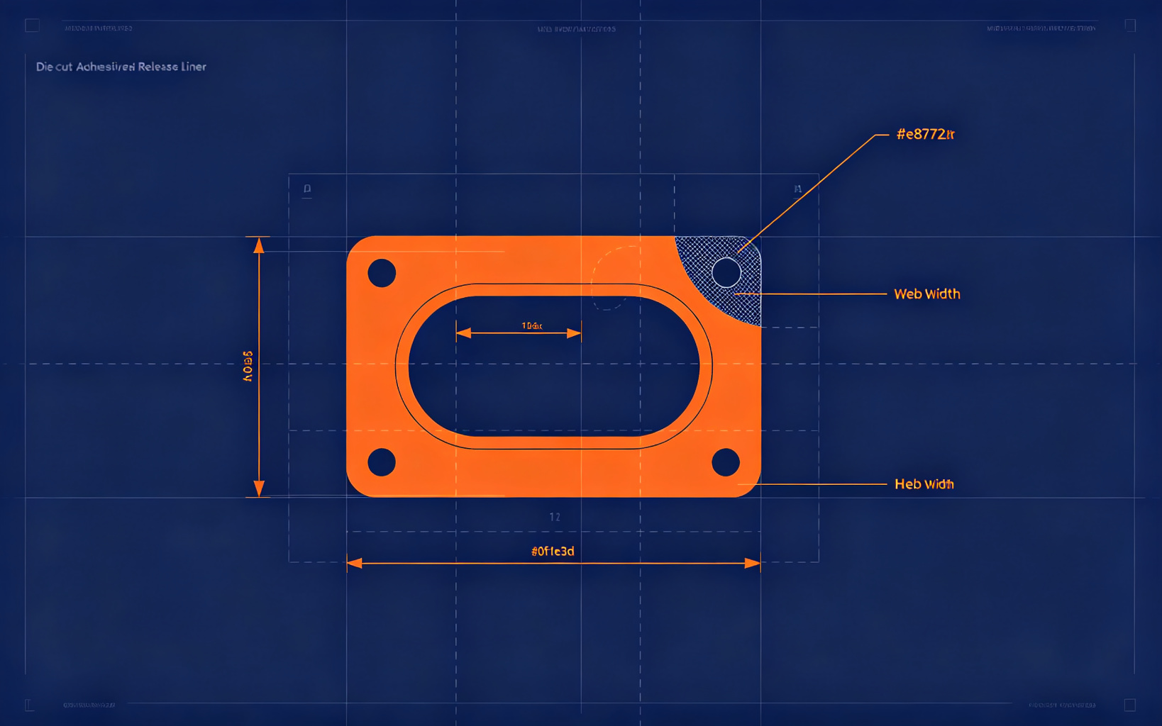
1. Minimum web and bridge width
Never design a web narrower than the material thickness (for film) or 1.5× the material thickness (for foam or rubber). A 0.1 mm PET web in a 1 mm foam part will tear on the matrix and force a re-tooling. When the part pattern has many holes, call out a minimum web on the drawing — it saves a design review cycle.
2. Inside corner radius
A razor knife cannot cut a true sharp inside corner without a radius. Specify an inside radius of at least 0.3 mm; on thick foams (≥1 mm), use 0.5 mm or larger. Sharp internal corners fracture the die steel and produce ragged edges. If a sharp corner is functionally required, plan a secondary post-punch step rather than expecting the die to do it.
3. Hole and cut-out size
The smallest reliably punched hole in film is roughly 1.5× the material thickness; in foam, 2× thickness. A 0.5 mm hole in a 1 mm foam pad will not hold tolerance and may bridge. Design holes larger than this, or switch to a rotary or laser process for micro-features.
4. Tolerance callout
Do not put ±0.05 mm on every dimension. That tolerance is achievable on flat-bed or laser cutting but not on high-speed rotary — and it doubles tooling cost. Put tight tolerances only on the critical mounting holes and assembly interfaces; leave general dimensions at ±0.15 mm (film) or ±10% thickness (foam).
5. Release liner and orientation
Specify which side faces up on the liner, the liner colour, and whether kiss-cut matrix needs grid lines for automated pickup. Missing these notes is the most common cause of a first article that does not match assembly expectations.
Send us your drawing before tooling. Our DFM team reviews it free and flags every dimension that will cost you money or delay the sample.
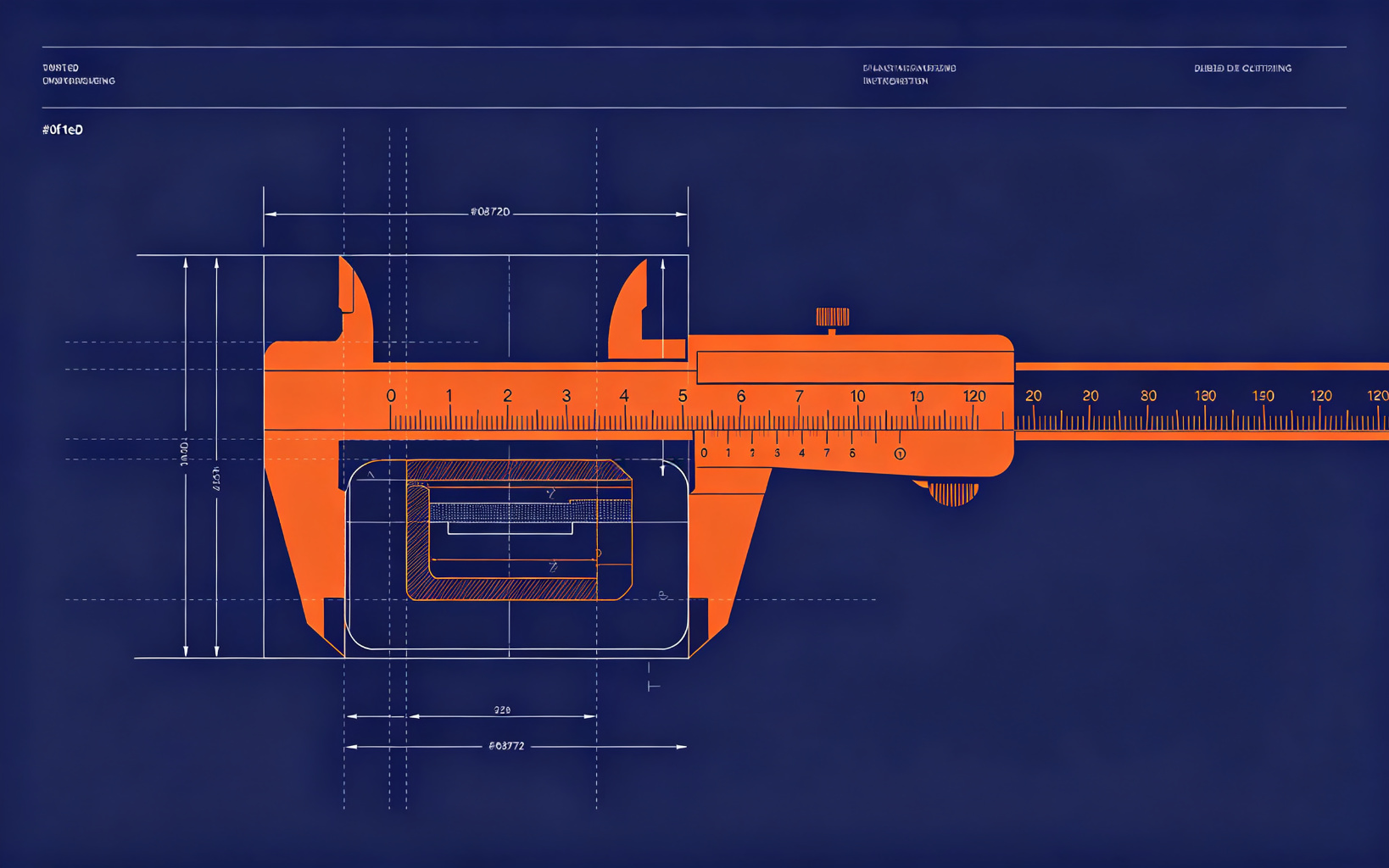
"What tolerance can you hold?" is the most common first question on a drawing — and the answer depends on which process cuts the part. Specifying a tolerance that the process cannot economically hold either raises price or produces rejections. Below are the working tolerances our shop holds in production.
1. Rotary die cutting
High-speed, lower cost, but the die is flexible and the material stretches slightly as it feeds. Expect ±0.10–0.15 mm on parts up to 200 mm; ±0.20 mm on larger nests. Ideal for high-volume consumer electronics where absolute precision is not the deciding factor.
2. Flat-bed (steel rule) die cutting
More rigid die, tighter tolerances: ±0.08–0.10 mm on small to medium parts, ±0.15 mm on larger nests. Slower than rotary, so the sweet spot is mid-volume production and first-article verification.
3. Laser cutting
No tooling cost and the tightest tolerance: ±0.05 mm or better on flat film up to about 500 mm. The trade-off is speed, edge char on foams, and a heat-affected zone that can matter on adhesive surfaces. Best for prototypes, low-volume custom parts and micro-features.
4. Thickness tolerance is separate
Part geometry tolerance is different from material thickness. On film, thickness is controlled to the adhesive manufacturer's spec (typically ±10%). On foam, expect ±10% to ±15% thickness, which matters when the foam must fill a precise gap. Specify the material grade, not just "black foam", to lock this in.
How to write the tolerance block
General linear: ±0.15 mm unless otherwise noted
Critical holes / datum features: ±0.05–0.08 mm (laser or flat-bed)
Common Die-Cutting Design Mistakes & How to Avoid Them
7 min read · Updated September 2026
After reviewing thousands of customer drawings, a small number of design errors account for most first-article surprises. If you recognise any of these on your drawing, fix it before tooling — it is cheaper than another sample round.
Mistake 1: Inside corners with zero radius
A die knife is a straight piece of steel bent to shape; it cannot produce a sharp internal corner without a radius. Expect ragged corners and broken dies if you call out 0 mm radius. Minimum 0.3 mm, preferably 0.5 mm on thick materials.
Mistake 2: Holes smaller than the rule
0.3 mm holes in 1 mm foam do not punch cleanly. The die bridge between adjacent holes also collapses if the web is under 1.5× material thickness. Either enlarge the features or switch to laser cutting.
Mistake 3: Tolerances copied from a machined part
Die cutting is not CNC machining. ±0.02 mm on every dimension forces flat-bed tooling and triples the unit cost. Reserve tight tolerances for the 2–3 dimensions that actually mate to another part; leave everything else at ±0.15 mm.
Mistake 4: No release liner specification
Leaving off liner side, colour and whether the part must stay on a carrier forces a guess. Automated assembly fails when the liner is the wrong side. Specify: "part face up on 75 µm blue PET liner, matrix grid every 50 mm".
Mistake 5: Selecting adhesive by peel strength only
A 200 oz/in peel number on the datasheet is measured on stainless steel at room temperature. On your oily PC enclosure at 85 °C the same tape may be far weaker. Specify substrate, temperature and cycle conditions — not just a peel rating.
Mistake 6: No material grade, only a brand colour
"Black foam gasket" is not a spec. The supplier will choose whatever is cheapest, and it may not match your compression or sealing requirement. Specify material family, thickness, density and a reference grade (e.g. "3M 4647 equivalent, 1.6 mm").
Most of these mistakes disappear in one drawing review. Send us your PDF — we annotate it with production notes at no charge.
Kiss Cutting vs Through Cutting: When to Use Each Process
5 min read · Updated September 2026
Kiss cutting and through cutting are not interchangeable options — they drive entirely different downstream assembly, tooling and cost. Choosing the right one at the design stage is cheaper than re-tooling after the first article.
Kiss cutting (die on the liner)
The knife cuts through the adhesive and carrier but stops cleanly on the release liner. The part stays on a continuous liner, in a fixed pitch, ready for robotic or roll-fed assembly.
Best for: high-volume consumer electronics, automated pick-and-place, parts that must be presented on a tape-and-reel liner.
Requires: tight liner thickness tolerance, accurate die depth control.
Watch out: thin foams can tear if the die cuts too deep; very soft materials may not release cleanly.
Through cutting (die through the part)
The knife cuts completely through adhesive, carrier and liner. The finished parts are loose, either bulk packed or on a easy-peel sheet.
Best for: low-to-mid volume, gaskets, foam pads, parts picked by hand, or parts where the liner is removed at final assembly.
Requires: a matrix (waste web) that holds the part during cut.
Watch out: parts move on the liner during stacking; tight pitch nests are harder than kiss-cut.
How to decide
Will a machine pick the part from a liner? → Kiss cut.
Will an operator peel and place it? → Through cut is cheaper and simpler.
Volume > 50,000 pieces per run? → Kiss cut pays back tooling cost fast.
Prototype or < 5,000 pieces? → Through cut, no need for precision liner tooling.
When you send your drawing, tell us how the part will be assembled. We will recommend the process that minimises total cost, not just unit price.